Review on Gigabyte B365M-DS3H Motherboard LGA1151-v2
4 min read - Image 1")
Hello everyone. Today in my review I will talk about the motherboard purchased to build a new computer. According to my plans, a new ninth generation Intel Core i5-9500f processor and a GeForce GTX 1650 Super graphics card will be installed in the new computer. The third, very important element of this system should be the motherboard, since it is on it that the above and other computer components are installed.
Initially, I chose from three options for the motherboard chipset.
 - Image 2")
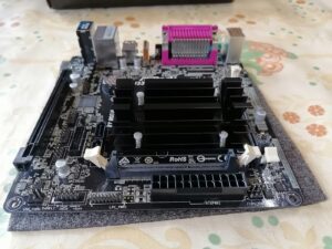
1. H310. These motherboards are the initial and most affordable motherboard option for ninth generation intel processors. These boards have a minimized power system, which may not cope with powerful processors such as Core i5 or Core i7 and can become very hot in subsequent use. Also on the motherboards of the H310 chipset there is no connector for connecting SSD drives of the M.2 format, which have a very high data transfer speed and allow the whole system to work much faster. In some motherboards, there are only two slots for installing RAM, which also limits, in a sense, the possibility of a subsequent upgrade. It was decided that H310 motherboards are not suitable for my system.
 - Image 3")
2. Z390. The most ideal motherboards for ninth generation intel processors. They make it possible to overclock the processor and RAM, which significantly increases the power of the entire system. Such motherboards are far from suitable for every user since using their advanced features requires some knowledge and a lot of patience. Well, the most basic drawback of Z390 motherboards is the high price. Since the processor I selected does not have an unlocked multiplier and its power cannot be increased, it was decided not to purchase the Z390 board.
 - Image 4")
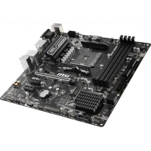
3. B365. This is the middle ground, since for the most part these cards have four slots for installing RAM, which may come in handy in the future. They also have a connector for high-speed SSD drive M.2, which allows you to assemble a system with quick response to your commands.
 - Image 5")
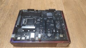
The GIGABYTE B365M-DS3H motherboard comes in small, original packaging. On the box cover in the form of icons it is indicated that the board supports the installation of processors of the ninth generation. The official website states that this motherboard supports the 9-th generation Core i3, i5 and i7 processors and you do not need to update bios for them, everything will work out of the box.
 - Image 6")
The motherboard is additionally sealed in a special package on which there is a kind of seal in the form of tape. On top of the board is a package with two sata cables that are used to connect hard drives.
 - Image 7")
Under the board in the box is the rest of the equipment. This is a driver disk, various documentation and a bracket used for installation in a computer case at the back where the main connectors of the motherboard are located.
 - Image 8")
The place for installing the processor is closed by a temporary plastic cover that bounces when the processor’s locking mechanism is closed.
 - Image 9")
 - Image 10")
 - Image 11")
 - Image 12")
 - Image 13")
 - Image 14")
 - Image 15")
 - Image 16")
 - Image 17")
 - Image 18")
 - Image 19")
 - Image 20")
 - Image 21")
 - Image 22")
Power for the processor on this motherboard is made on the principle of 8 pin. In some expensive motherboards, this connection additionally has another 4 pin connector.
 - Image 23")
There are three 4 pin connectors on the board for connecting case fans. One of the connectors is designed to connect the processor cooling system, and the other two connectors can be used at your own discretion.
 - Image 24")
The board has four slots for installing RAM modules. In pairs, these connectors are painted in a different color, which allows you not to make a mistake when installing the memory modules in the right order, namely A1 and A2 or B1 and B2.
 - Image 25")
The motherboard power connector has a 24 pin connector. When connecting the power cable from the unit to this connector, you need to be careful since using excessive force can break the PCB.
 - Image 26")
The sata connectors on the motherboard are in direct orientation, which is a bit inconvenient when connecting the sata cable. There are 6 such connectors on the board.
 - Image 27")
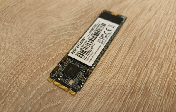
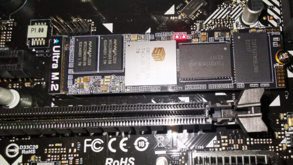
The main connector for connecting a video card has a plastic design and a latch that does not inspire confidence in quality. The M.2 connector is located a little higher, which in my opinion is a drawback since all the heat from the video card will be in contact with the SSD M.2 disk, which is very harmful for it.
 - Image 28")
The remaining connectors and connectors do not deserve special attention since they have a standard layout and functionality. Installing the motherboard in the case and subsequent installation of the remaining components on it was successful without any problems. After the build, the whole system started the first time. The latest version of bios was installed on the motherboard. The operating system booted and installed very quickly and without problems. Frankly, for my many assemblies I try to use GIGABYTE motherboards and they have not let me down yet.
The article is written on the basis of materials of this site.


Suitable for budget PC. But Very poor design. after installing the graphics card, the retention levers of Memory slots get stuck to the graphics card, and to change any Memory you have to remove the graphics card, BUT to remove the graphics Card the PCIE16 slot security lock latch must be released, but the latch is located at the bottom, that’s next to the motherboard’s Chipset heatsink, and since most graphics cards fill two slots, it cannot be pulled with any ease. Also, after installing the graphics card, both PCIE1 and PCIE4 slots become unusable. The PCIE1 slot is buried under the graphics card, PCIE4 can be used to install small cards, but it will cover the graphics card fan and might cause damage to it. On other motherboards, if they have a PCIE4 slot, you may use it to install any PCIE card (1x, 4x, 8x or even 16x) but on this motherboard, the chip heatsink blocks the way and you won’t be able to install any 16x or 8x cards. The printed user manual in the box is very brief and the full version must be downloaded from the web site. Also, The Memory slot numbers on the motherboard are printed in reverse order, so DDR4_4 is actually DDR4_1.